Build any section
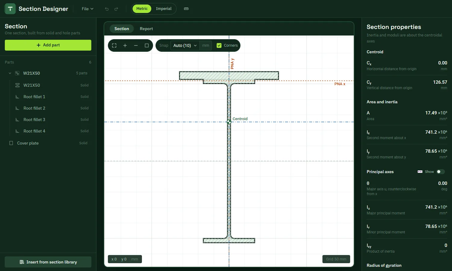
Rectangles with optional rounded corners, circles, semicircles, I, T, channel and angle shapes, root fillets and polygons you draw point by point. Any part can be a hole.
 TekStructa
Cross-section properties
Build any cross-section from standard parts, hot‑rolled and cold‑formed steel sections to AISC and AISI, your own polygons or a DXF outline, and get its area, centroid, moments of inertia, elastic and plastic section moduli, principal axes, torsion constant and warping constant as you edit.
Features
Rectangles with optional rounded corners, circles, semicircles, I, T, channel and angle shapes, root fillets and polygons you draw point by point. Any part can be a hole.
Hot-rolled shapes from AISC (W, S, C, MC, single and double angles, HSS and pipe) with root fillets and corner radii, and cold-formed C‑sections, studs, joists and tracks from AISI with rounded bends.
Area, centroid, Ix, Iy and Ixy, principal moments and angle, radii of gyration, elastic section moduli to every extreme fibre and plastic section moduli.
Torsional constant J, warping constant Cw and the shear centre by finite element analysis, for open, closed and built-up sections.
Drag, rotate and mirror parts with snapping to corners and intersections. Group parts, copy and paste, undo and redo.
Import a closed outline from a DXF file, export the section as DXF, download a summary or step-by-step PDF report, and work in metric, imperial or custom units.
Method
Get started
Add parts, insert a standard steel section (AISC or AISI), draw a polygon or import a DXF outline.
Set each part's dimensions and position, or drag it on the canvas. Mark parts as holes where needed.
Read the properties as you edit, and show the principal and plastic neutral axes on the canvas.
Download the summary or step-by-step PDF report, or export the section as DXF.
Quick calculators
Symmetric and unsymmetric I sections: Ix, Iy, S, Z and r, with the hand calculation step by step.
Rectangular and square tubes with rounded corners, matching the AISC HSS tables, J included.
Channels with flat flanges: centroid, Ix, Iy, S, Z and r, with the hand calculation step by step.
Tees: centroid, Ix, Iy, section modulus at the flange and the stem, and the plastic neutral axis.
Equal and unequal angles: Ix, Iy, product of inertia, principal axes and Iz, checked against AISC.
Solid rectangles: Ix, Iy, S, Z and r, and the exact torsion constant J.
Round tubes, pipe and solid circles: I, S, Z, r and J, matching the AISC round HSS tables.
From the blog
A C12X20.7 modelled as rolled gives Cw = 87 in⁶ against the table's 112 in⁶. Why both are right, and which to use.
How to calculate S and Z, with a rectangle and a T section worked out, and the shape factors of common sections.
Why a 4CS2.5x105 with 14% less steel than a C3X4.1 has 60% more Ix, and the catch with thin walls.
FAQ
Area, centroid, moments of inertia Ix, Iy and Ixy, principal moments and angle, radii of gyration, elastic section moduli to each extreme fibre, plastic section moduli with the plastic neutral axes, torsional constant J, warping constant Cw and the shear centre.
Yes. Add as many parts as you need: overlapping solid parts are merged into one section and hole parts are cut out, so built-up girders, plated beams and sections with openings all work.
Yes, from different standards. Hot-rolled shapes from the AISC Steel Construction Manual, 16th Edition: W and S shapes, C and MC channels, single and double angles, rectangular, square and round HSS and pipe, with their root fillets and corner radii. Cold-formed steel C‑sections with and without lips, including studs, joists and tracks, from the AISI Cold-Formed Steel Design Manual, with their rounded bends.
By a finite element warping analysis of the actual cross-section, so they are accurate for open, closed and built-up shapes, not only thin-walled approximations.
Yes. The app is free to use in your browser while TekStructa is in beta. There is nothing to install.
More apps
Free PM Interaction Diagram Calculator
📐Free RC Beam Design Calculator
📏Free Beam Calculator: Reactions, Shear, Moment and Deflection
For use by qualified engineers. All results must be checked independently before use in any design. See the Terms of Use.